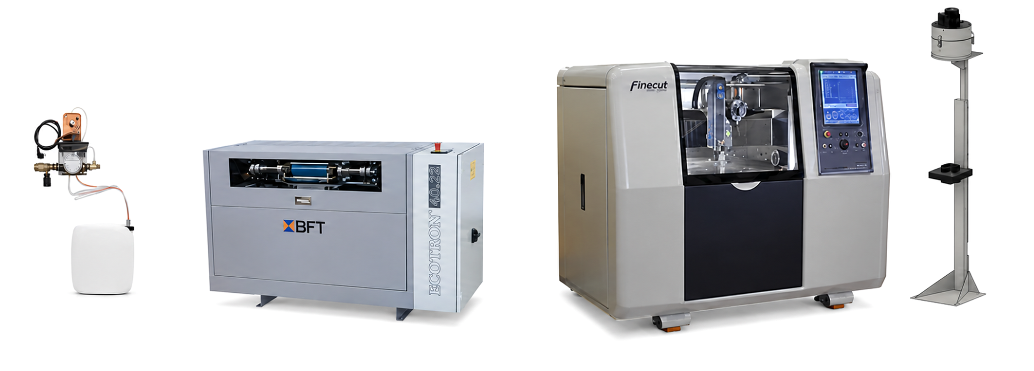
One coordinated delivery.Finepart develops and manufactures the precision machine and coordinates the complete Finecut System—from factory acceptance and installation to training, documentation and lifecycle support.
Machine developmentFinepart
Factory acceptanceMölnlycke, Sweden
Support coordinationFinepart HQ, Sweden
System responsibility
Who develops and manufactures the system?
Finepart's core business is the development and manufacture of micro abrasive waterjet machines: Finecut µCUT, Finecut WMC500II, Finecut WMC1000II and Finepart Taylor Made solutions.
01 · The machine platform
Developed and manufactured by Finepart
Finecut WMC500II is Finepart's flagship modular platform. It can be supplied in 3-, 4- or 5-axis configurations, and compatible WMC500II systems can be reviewed for later upgrades. All multi-axis configurations can also operate in 3-axis mode.
Finecut µCUT is a fixed 3-axis configuration and is not upgradeable. Finecut WMC1000II is configured for the application, while Finepart Taylor Made is engineered around requirements beyond the standard platforms.
02 · The complete Finecut System
Machine, utilities, software and competence
A complete Finecut System combines the precision machine with the equipment and knowledge required for operation. Depending on the agreed system scope, this includes a high-pressure pump, mist extraction, water stabilisation, CAD/CAM software and a training package from Finepart Academy.
These supporting products are manufactured and supplied by Finepart's partners. Finepart coordinates the delivery and takes responsibility for system functionality and training within the scope defined in the quotation and agreement.
Acceptance process
FAT before shipment. SAT after installation.
Acceptance is structured to verify the agreed system before it leaves production and again after installation at the customer's site.
01
Factory Acceptance Test · FAT
Before delivery, the system undergoes Finepart's standard FAT at the production operation in Mölnlycke. The test verifies the system against the deliverables and specifications defined for the order. The customer is welcome to attend.
02
Installation
After arrival, the Finecut System is installed and prepared for verification at the customer's site.
03
Site Acceptance Test · SAT
The SAT reflects the FAT and confirms that the delivered system has arrived, been installed and performs in accordance with the agreed acceptance scope.
04
Customer acceptance
Customer approval completes the acceptance stage. The quotation, agreement and applicable delivery terms govern the formal completion of delivery and the transfer of title and risk.
Installation planning
What to consider when installing a micro abrasive waterjet.
Getting a Finecut System operational requires coordinated preparation of the site, utilities, handling equipment and ambient environment. Finepart confirms the final requirements for the ordered machine, high-pressure pump and associated equipment.
Within two weeks of orderSubmit the facility layout
Show the intended position of every machine, pump and associated unit.
Before deliverySubmit the water analysis
Finepart checks whether the standard treatment system is suitable.
Before installationComplete every utility point
Power, mains water, drainage and compressed air must be ready.
When equipment arrivesUnload every transport box
The customer provides safe unloading and internal transport at each delivery.
01Electricity
Separate, project-specified supply points.
02Mains water
Minimum inlet pressure 4–7 bar, depending on pump configuration.
03Mains drain
Drainage at the agreed equipment locations.
04Compressed air
Minimum 6.5 bar, dry and oil-free.
If the available water pressure is insufficient, Finepart can propose a suitable technical solution. For installations with more than one Finecut System, separate supply points for all required services must be provided for each machine, each high-pressure pump and all associated equipment.
Regional configurations
EU and US installations are different.
Power supply, frequency and installation details depend on the market configuration. Do not transfer values between CE and US installations. Finepart confirms the applicable requirements in the order-specific documentation.
CE configurationEuropean UnionMetric
Finecut power
400 V · 50 Hz · 25 A
High-pressure pump power
400 V · 50 Hz · 60 A
Mist extraction
Powered from the Finecut machine
Maximum pump distance
100 m to the Finecut machine
Pump inlet water
4–7 bar
Pump operating temperature
5–35°C
Compressed air
Finecut 6.5 bar · pump 5–7 bar
Water stabilisation
24 V, powered from the high-pressure pump
US configurationUnited StatesImperial
Finecut power
230 V · 60 Hz · 25 A
High-pressure pump power
480 V · 60 Hz · 60 A site supply
Mist extraction
Powered from the Finecut machine
Maximum pump distance
109 yd to the Finecut machine
Pump inlet water
4–7 bar · 58–101 psi
Pump operating temperature
41–95°F · 5–35°C
Compressed air
Finecut 6.5 bar · pump 5–7 bar
Water stabilisation
24 V, powered from the high-pressure pump
For both configurations: compressed air must be dry and free from oil and dust. Water or oil cooling may be available depending on the selected pump configuration.
Footprint, access and handling
Plan for the complete equipment envelope.
Dimensions and weights differ between market configurations and pump suppliers. Allow additional service, ventilation and door-opening space around the stated equipment dimensions.
Example system configuration shown with the compact BFT high-pressure pump. The final equipment arrangement and pump selection are order-specific.
Equipment
EU planning dimensions
EU planning weight
US planning dimensions
US planning weight
Additional clearance
Finecut WMC500II
2,090 × 1,300 × 1,750 mm
2,500 kg
6 ft 9 in × 4 ft 4 in × 5 ft 9 in
5,511 lb
Two doors: 500 mm / 20 in each when open
BFT high-pressure pump
1,800 × 800 × 1,050 mm
Approx. 830 kg*
5 ft 11 in × 2 ft 8 in × 3 ft 6 in
1,786 lb
Allow space for cooling and service access
UHDE high-pressure pump
2,220 × 1,050 × 1,460 mm
1,210 kg*
Order-specific
Order-specific
Allow space for cooling and service access
Mist-extraction unit
440 × 440 × 2,420 mm
Confirm for delivery
18 × 18 × 95 in
Confirm for delivery
Height is adjustable
*Planning/transport values shown in the system footprint overview. The dedicated pump technical sheets state 810 kg for BFT and 1,100 kg for UHDE; use the order-specific shipping documents when selecting unloading and lifting equipment.
Typical shipment20-foot container or truck
Delivered formatSeveral large, heavy boxes
Customer responsibilityUnload each delivery safely
High-pressure pump alternatives
UHDE and BFT require different planning.
Both pump platforms deliver the high-pressure water required by the Finecut process, but their dimensions, weight, oil capacity and installation data differ.
UHDE 4022Longer, heavier platform
Maximum water flow
2.3 l/min
Maximum pressure
4,000 bar
Maximum noise level
78 dB(A)
Cooling system
Oil/air; water cooling on request
Attenuator
TÜV-certified · 2.0 litres
Technical dimensions
2,210 × 1,045 × 1,335 mm
Technical weight
1,100 kg
Oil-tank volume
200 litres
Power output / consumption
22 kW / 27.2 kW at maximum pressure and flow
BFT 40.22 · US denomination 60.30More compact footprint
22 kW · 30 hp / 27.2 kW at maximum pressure and flow
US BFT electrical planning
The detailed pump sheet states three-phase 480 V / 60 Hz, rated current 40 A and recommends a 50 A fuse. The system footprint overview specifies a 60 A pump supply. Final circuit sizing, protective devices and local-code compliance must therefore follow the order-specific electrical documentation and a certified electrician's assessment.
01 · Layout & utilities
Plan the complete installation
Submit a facility layout no later than two weeks after order confirmation.
Show each Finecut machine, high-pressure pump and associated unit in its intended position.
For multiple systems, provide separate utility supply points for every machine, pump and associated unit.
02 · Floor & access
Prepare for size and weight
The installation floor must be flat within ±10 mm and free from vibration.
Confirm that the access route can accommodate all large and heavy transport boxes.
Delivery is normally made by truck or in a 20-foot container. The customer is responsible for unloading every delivery.
03 · Electrical & mounting work
Provide qualified local trades
The customer provides a certified electrician for connection to the facility's electrical supply.
Finepart works carefully and professionally at the site, but the customer is responsible for drilling any required floor-mounting holes.
Final connection details must follow the project-specific installation documentation.
04 · Network connection
Coordinate with your IT team
Any connection to the customer's internal computer network is the customer's responsibility.
Network access should be planned with the customer's IT and security requirements in mind.
Confirm the agreed connection method before commissioning.
05 · Operating environment
Protect precision and stability
Maintain an operating temperature between 10°C and 35°C.
Provide sufficient air circulation for the oil/air pump cooler when installed.
For optimum performance and full use of the positioning accuracy, maintain a stable ambient temperature around 20°C and relative humidity at or below 50%.
06 · Storage
Prevent freezing damage
If the system is stored before installation or later during its service life, keep it above 5°C.
Protect the equipment from freezing conditions throughout storage and handling.
Contact Finepart before restarting equipment that may have been exposed to temperatures below the specified limit.
Operating range10–35°C
Maintain sufficient air circulation.
Optimal precision≈20°C
Stable ambient temperature.
Relative humidity≤50%
Recommended for optimum performance.
Storage>5°C
Protect the system against freezing.
Cutting-water quality
Protect the high-pressure system.
Water quality has a direct effect on maintenance intervals, wear in nozzles, swivel joints, control valves and high-pressure seals, and therefore on operating cost and productivity. A water analysis must be submitted to Finepart before delivery.
If the analysis falls outside the capability of the standard water-treatment system included with the Finecut System, Finepart can propose suitable additional equipment.
The values below support installation planning. Finepart reviews the customer's water analysis and confirms the project-specific treatment requirements.
Recommended cutting-water quality
Parameter
Acceptable
Good
Alkalinity (mg/l)
25
10
Carbon dioxide (mg/l)
0
0
Chloride as Cl (mg/l)
15
1
Copper (mg/l)
2.0
2.0
Free chlorine (mg/l)
1
0.05
Electrical conductivity (µS/cm)
100–450
100–450
Iron as Fe (mg/l)
0.1
0.01
Manganese as Mn (mg/l)
0.1
0.05
Magnesium as Mg (mg/l)
0.1
0.1
Nitrate (mg/l)
25
10
pH
7.0–8.5
7.5–8.5
Silica (mg/l)
5
1
Sodium (mg/l)
10
1
Sulfate (mg/l)
25
1
Total dissolved solids, TDS (mg/l)
100
5*
Total hardness as CaCO3 (mg/l)
2–10
2–5
Turbidity (NTU)
1.5
0.5
*For TDS, values below 5 mg/l may make the water too aggressive.
Customer prepares
The facility and local resources
Facility layout, water analysis, unloading and internal transport, suitable floor and access, utility supply points, network connection, floor drilling, a certified electrician and compliance with local pressure-equipment requirements.
Finepart supports
The system installation
Finepart confirms the project requirements, reviews the water analysis, proposes additional technical solutions when needed and performs the agreed installation and commissioning work for the delivered Finecut System.
Always use the order-specific requirements.
This page is an early planning guide. The signed quotation, approved facility layout and project-specific pre-installation documentation define the final requirements for the selected Finecut System, high-pressure pump and associated equipment.
Every purchased Finecut System includes training matched to the delivered machine and configuration. The programme forms part of Finepart Academy and combines theory with practical, hands-on learning.
01Waterjet fundamentals
The principles and conditions behind waterjet cutting.
02Micro abrasive waterjet
How the process changes when precision, kerf and component scale become critical.
03The Finecut process
Operation and process understanding relevant to the purchased system.
04CAD/CAM
Relevant instruction in the CAD/CAM software used to prepare and run the cutting process.
Consumables, spare parts, service and technical support are coordinated from Finepart's headquarters in Sweden, with selected service partners supporting customers in parts of the world when appropriate.
01How are consumables, spare parts and service handled?
Orders and service requests are coordinated from Finepart's headquarters in Sweden. Standard spare parts that are in stock are normally dispatched the same day or the following business day, depending on availability and when the order is received.
Technical support is coordinated from Finepart's headquarters in Sweden. Finepart may also use selected service partners to support customers in different regions.
Each system is delivered with manuals for the included equipment and the certificates and documentation that form part of the agreed delivery.
04How are drawings and customer information protected?
Finepart is prepared to enter into a confidentiality agreement with potential customers. Finepart normally prefers a Mutual NDA because both parties may need to disclose information that should be protected. Drawings received under that framework are handled within Finepart's operational sphere and are not intended for distribution outside it.
05Which quality requirements and certifications apply?
Finepart builds its machines according to its Standard Operating Procedures and the applicable requirements for CE conformity. In the Finepart demo centre, customer-specific processes may also be followed when agreed for a particular project.
The exact standards, certificates and documentation included are defined for each delivery.
Start with the application
Define the system around your part.
Share the material, drawing, tolerance and production requirement. Finepart will evaluate the application and propose the appropriate validation and system scope.