In this article we cover definition of kerf, kerf angle, what you need to know about kerf and taper, what affects the kerf, and how to adjust your waterjet machine to compensate for the kerf angle.
What is kerf?
The definition of kerf is the gap or slot created by the cutting tool as it removes material from the workpiece. It represents the width of the material that is lost during the cutting process. The width of the kerf depends on various factors, including the type of cutting tool, the material being cut, and the cutting parameters used. Achieving the desired kerf width is essential for achieving the required specifications of the final product.
What is kerf width?
The kerf width primarily depends on the diameter of the jet but it is also affected by the time the material is exposed to the jet.
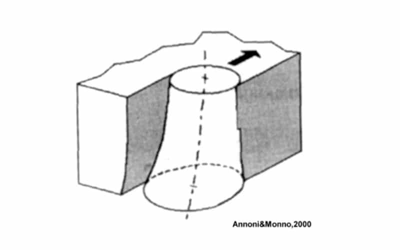
The center part of the kerf will be subjected to more particle impacts in the abrasive waterjet cutting process compared to near the sides of the kerf. This will result in quicker material removal at the centre and less removal at the sides. Consequently, the width of the cut will be wider at the top than at the bottom.
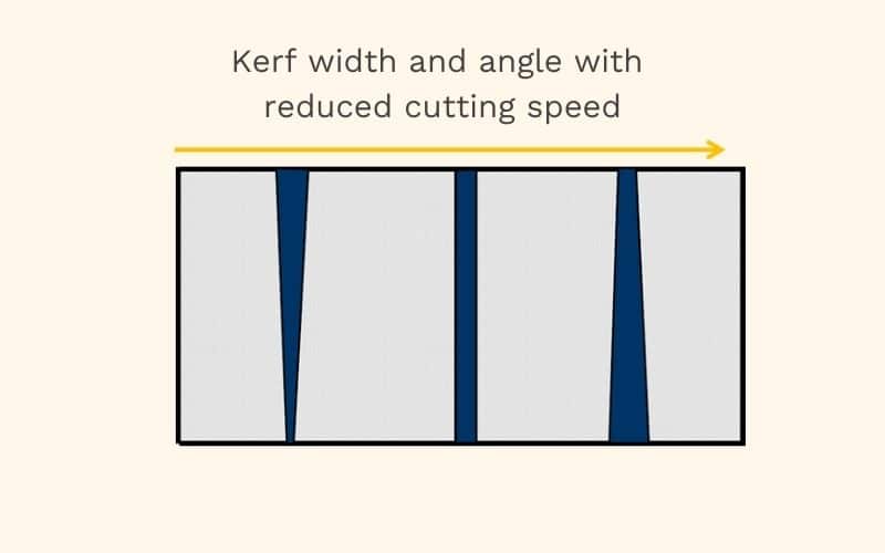
If the feed rate (cutting speed) is reduced and there is more jet stream exposure time, more material towards the bottom will be removed. As the jet will exhibit a diverging shape, the kerf will also become wider at the bottom with reduced feed rates.
Factors influencing kerf width
Several factors can affect the width of the kerf:
- Firstly, the type of cutting tool plays a significant role. Different tools, such as saw blades, lasers, or waterjets, have varying kerf widths associated with them.
- Additionally, the material being cut can impact the kerf width. Harder materials may result in a wider kerf compared to softer materials.
- Cutting parameters, such as feed rate and cutting speed, also influence the kerf width.
It is important to optimize these parameters to achieve the precision and cut quality of your final product.
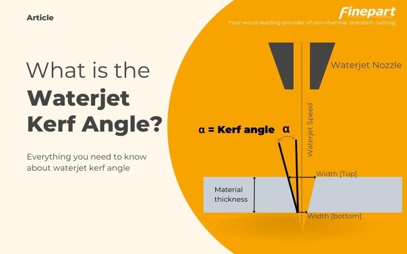
What is waterjet kerf angle?
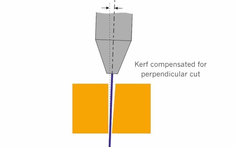
In addition to the kerf width, the abrasive waterjet cutting process also introduces a kerf angle. The kerf angle refers to the taper or beveled edge that occurs on the cut surface due to the nature of the waterjet stream. The kerf angle can vary depending on factors such as the type of material, material thickness, the waterjet pressure, the waterjet nozzle design, and the cutting speed. It is important to consider the kerf angle, especially when precise vertical cuts are required.
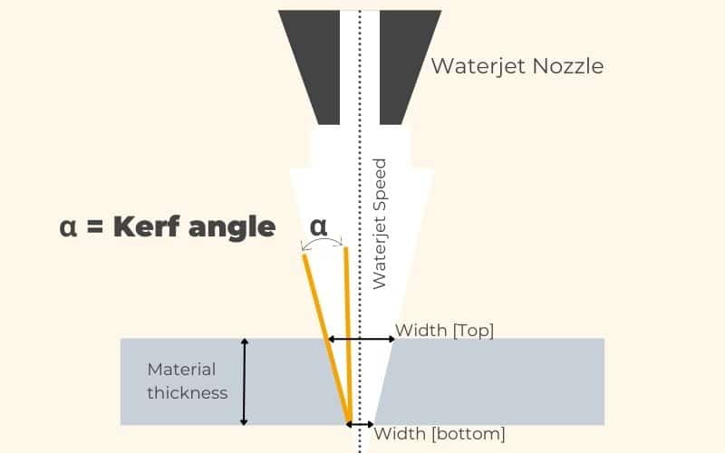
The kerf taper angle is the angle of the kerf side compared to the perpendicular edge. With a kerf that has a different width at the top, compared to the kerf at the bottom, the taper angle is defined as one half of the included angle of the two sides. By tilting the waterjet angle, equal to the kerf angle, the part will get a perpendicular edge.
What tolerance can an abrasive waterjet hold?
For a well aligned and coherent jet the programmed to avoid dynamic form errors a tolerance of ca +/- 10 µm can be achieved.
The abrasive waterjet is a dynamic tool having its shape determined by the interaction between the energetic jet and the material being exposed to the cutting action. Besides a taper the waterjet typically also exhibits some lag, and in case of high feed rates also a pendulum action. This jet shape deviation will cause a discrepancy between the top of the kerf and the bottom of the kerf, which limits the tolerances due to form errors related to the jet dynamics.
More about waterjet tolerances
BEYOND CUTTING EDGE
Finecut Micro Waterjet Series
Easy to operate 3, 4, and 5 axis micro waterjet machinery for high precision cutting stainless steel parts with ultimate edge and surface finish in one single process.